Synth Section
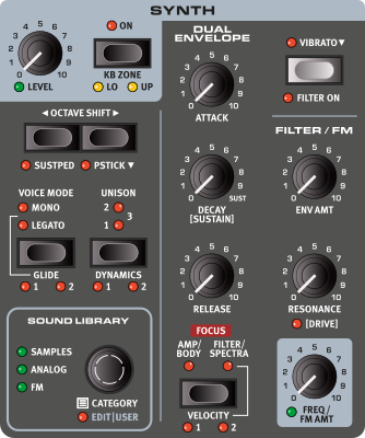
ON/OFF AND LEVEL
The Synth section is turned On or Off by pressing its ON button and its output volume level is controlled by the LEVEL knob.
The Level can by controlled by an attached expression pedal, such as the Nord EP15 or EP30, in which case the LEVEL LED will be lit. See Program Section for details on how to set this up.
KB ZONE
Press KB ZONE (Shift+On), to assign the Synth section to any of the active keyboard zones. The green LEDs indicate whether the Layer is assigned to the LO (lower), UP (upper) or both keyboard zones. Read more about Split setups and keyboard zones.
OCTAVE SHIFT
Use OCTAVE SHIFT ◀︎ / ▶︎ to transpose the Synth section up or down by octaves (+/- 12 semitones). When assigned to the entire keyboard it can be transposed two octaves up or down. When assigned to a smaller zone the available transpose values will vary, but always provide access to the entire range of the Synth.
SUST PED
SUST PED (Shift+Octave Shift Down) activates any attached sustain pedal for the Synth section. Read more on how to configure attached pedals in the Menus chapter.
PSTICK (73/HP)
PSTICK activates the Pitch Stick for the Synth section. By default the pitch bend range is -2/+ 2 semitones, but other options are available by pressing and holding down Pstick (Shift+Octave Shift up).
Range, semitones: ±1, -±2, ±3, -±4, -±5, ± 7, ±10, ±12, -12/+2, -24/+2
VOICE MODE
With the MONO or LEGATO voice mode active, only one note is played at a time, like on a traditional monophonic synthesizer. In Mono mode the envelopes are retriggered with each stroke whereas they are only retriggered with detached (“non-legato”) strokes in Legato mode.
When none of the Mono and Legato LEDs are lit, the Synth section is in its default polyphonic mode.
GLIDE
The GLIDE function makes the pitch “glide” from one note to the next when playing (traditionally referred to as portamento) and is available in Legato and Mono voice mode only. The 1, 2 and 3 (both LEDs being lit) settings provide three different Glide times to choose from.
UNISON
The UNISON feature creates an ensemble-like sound by combining multiple, slightly detuned and stereo panned, voices. For samples, notes are borrowed from neighbouring keys in order to achieve a natural and rich sound.
There are three different degrees of Unison, 1, 2 and 3, each providing an increasing degree of detune and stereo spread.
DYNAMICS
For Samples, each DYNAMICS setting; 1, 2 and 3, gives the sample instrument an increased dynamic range. When Dynamics is turned off, most velocity controlled parameters, including preset filter settings are deactivated.
For Analog and FM sounds, the Dynamics control determines the amplitude velocity sensitivity.
VIBRATO
Press VIBRATO (Shift+Octave Up) to activate the Synth vibrato, using the settings made in the Vibrato menu – accessed by holding down Vibrato:
Rate: The Rate (speed) of the vibrato has a range of 2 to 8 Hz.
Amount: The Amount parameter determines the strength of the vibrato and can be set to values between 0 and 10.
Delay: When set to Off, the vibrato takes effect instantly as a note is played. With a Delay time set, the Vibrato is introduced 0.1-3.0 seconds after a note is played.
When a Sample or Preset is loaded, settings for Vibrato Rate and Amount are loaded as part of the Preset.
SYNTH VIBRATO WHEEL (73/HP)
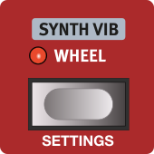
The SYNTH VIB WHEEL button at the far left of the panel can be used for assigning the Modulation Wheel to Synth Vibrato. When turned on, this function overrides any permanent or delayed Vibrato that is set up in the Synth section.
SYNTH VIBRATO (61)
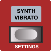
The SYNTH VIBRATO button at the far left of the panel can be used for applying Vibrato in real time. Pressing Shift+Synth Vibrato provides a shortcut to the Rate/ Amount settings page.
SOUND LIBRARY
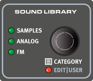
The SOUND LIBRARY area allows for selecting Preset sounds using Samples, Analog and FM respectively. The Sound Library dial also gives access to detailed settings for a selected Analog or FM sound, allowing for creating sounds from scratch or fine tuning a preset sound as desired.
SELECTING A PRESET
With the Synth section turned On, press the SOUND LIBRARY dial once to display a list of available Preset categories.
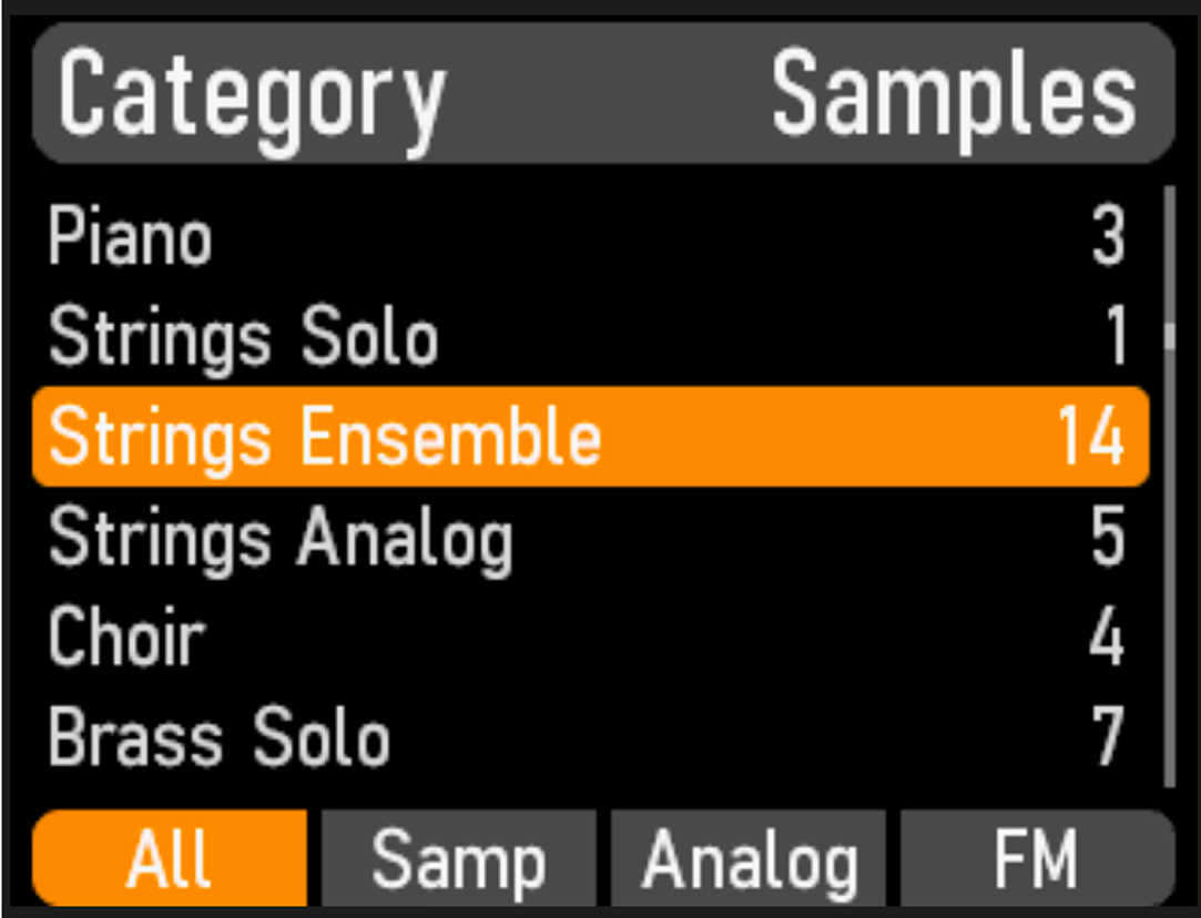
Use the display soft buttons to select between ALL, SAMPLES, ANALOG and FM respectively. The category list adapts to the selected type.
Select the desired category using the dial and press again to display the available Presets within that category.
Once a preset has been selected, press the dial again to confirm the selection and exit the list, or SHIFT/EXIT to return to the category list for further browsing.
EDIT|USER (SHIFT+SOUND LIBRARY DIAL)
Pressing EDIT|USER (Sound Select dial in combination with Shift) enters the manual Samples, Analog and FM views respectively. See the Samples, Analog and FM sections further below for details on settings within these views.
In Edit view, pressing Shift and the Sound Library dial again switches between Samples, Analog and FM, giving direct access to each type without having to select a Preset first. This is useful for quickly setting up a sound from scratch.
ABOUT PRESETS
A selected Preset, regardless of type, comes with preset settings for all Synth section functions, including both envelopes, the Filter, Dynamics, Vibrato and more. These settings can be adjusted as desired, and the adjusted sound can be stored as part of a Program.
The Preset banks within the Synth section are “read-only” and are not possible to store to directly.
SAMPLES
The Nord Electro 7 comes with a wide range of samples from the Nord Sample Library. Additional samples can be downloaded using the Sound Library feature of the Nord Sound Manager, and custom user samples can be created and downloaded using the Nord Sample Editor 4.
In order to download new samples, it may eventually become necessary to free up space in the instrument's sample memory. This can be done from the Nord Sound Manager, either by removing unused samples – that are not part of any stored programs – or by using the Relink or Substitute function which keeps programs intact while replacing samples.
Like other Synth Presets, Samples are loaded with preset settings for the Amp Envelope, Dynamics and Vibrato. The Filter is automaticaly turned Off when a Sample preset is loaded, but can be turned on and used if desired by pressing FILTER ON (Shift+Vibrato). Read more about the Filter.
ABOUT THE SAMPLES EDIT VIEW
To access the Edit View for SAMPLES, press EDIT|USER (Shift+Sound Library dial). Settings in the Edit View are selected using the soft buttons, and changed using the PROGRAM dial.
PAGE 1 – PRESERVE EDITS
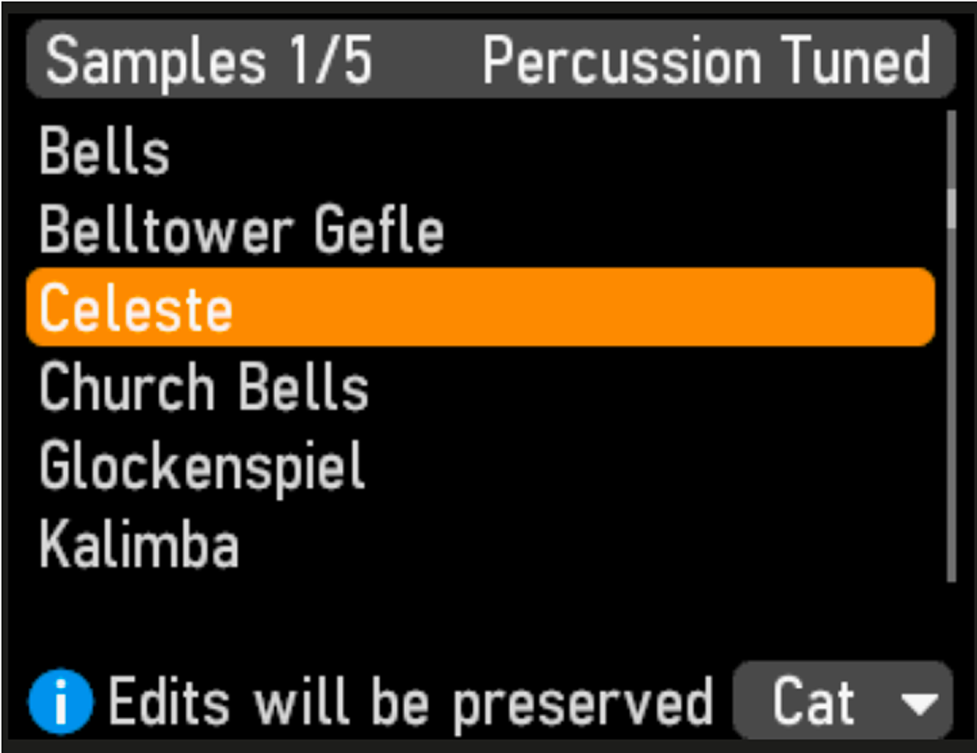
From the first page of the Samples Edit view, it is possible to select a different sample while keeping all panel settings intact. This is different from when loading a sample preset from the Sound Library, in which case Envelope, Filter, Velocity and other settings are overridden or turned off based on the preset values.
Use the PROGRAM dial to select the desired sample and press down the Cat soft button to navigate different categories.
PAGE 2-5 – ENVELOPES AND FILTER
The Envelope and Filter pages for Samples are identical to those found in Edit View for an Analog sound – please refer to the next section for further reading about these.
ANALOG
The Nord Electro 7 features a powerful yet compact Virtual Analog synth, based on a dual oscillator and dual ADSR envelope architecture with the addition of a resonant low-pass filter with adjustable keyboard tracking and filter Drive. Read more about all of these functions below.
ABOUT THE ANALOG EDIT VIEW
To access the Edit View for an ANALOG synth sound, press EDIT|USER (Shift+Sound Library dial). Settings in the Edit view are selected using the soft buttons, and changed using the PROGRAM dial.
The Edit View contains a number of pages, each grouping together related parameters.These are all outlined below, and are navigated using the PAGE buttons.
PAGE 1 & 2 – OSCILLATOR
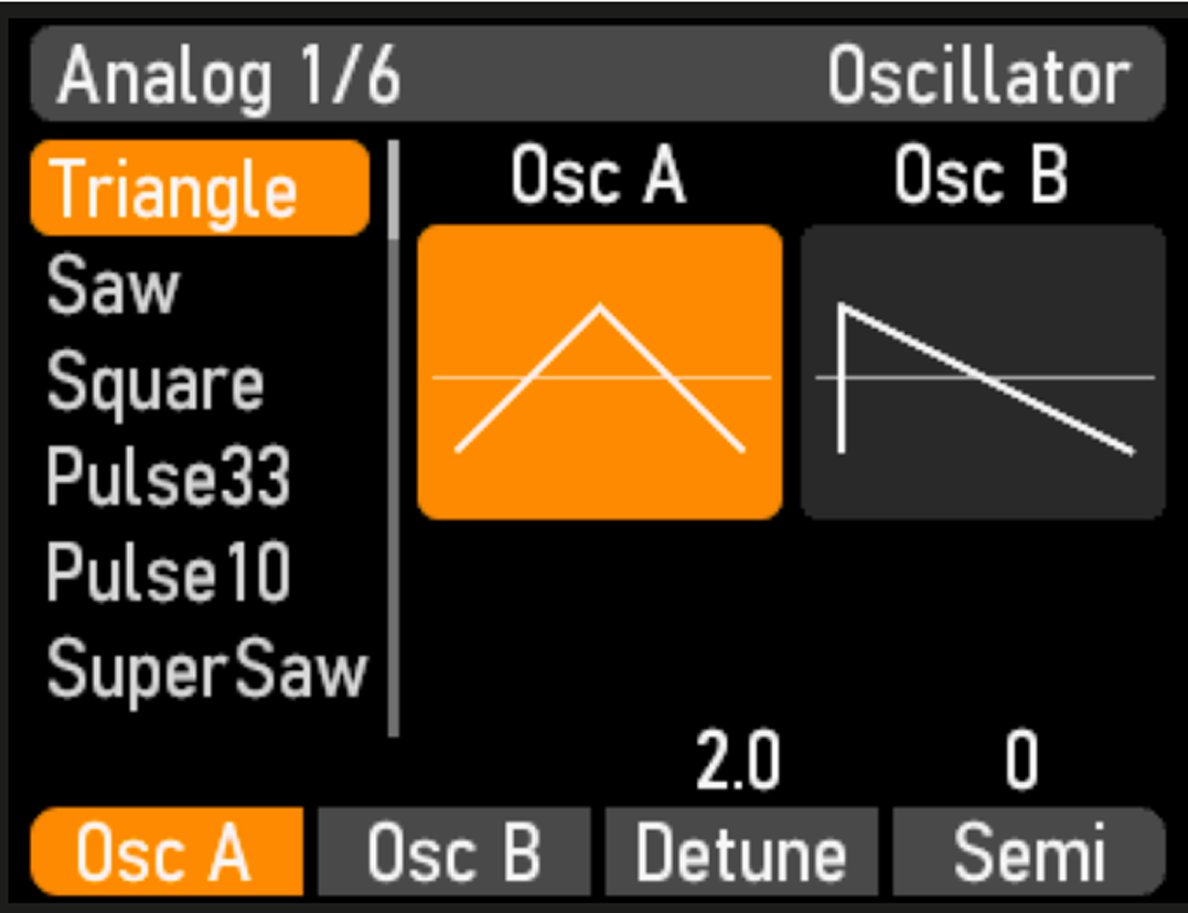
OSCILLATORS A AND B (OSC A, OSC B)
The two available oscillators – A and B – are focused for editing using the Osc A and Osc B soft buttons.
Oscillator A has six waveform options to choose from, including a multioscillator Super Saw. Oscillator B instead has a White Noise option.
When Super Saw is selected for Oscillator A, Oscillator B including the Semi and Mix (Page 2) parameters are disabled.
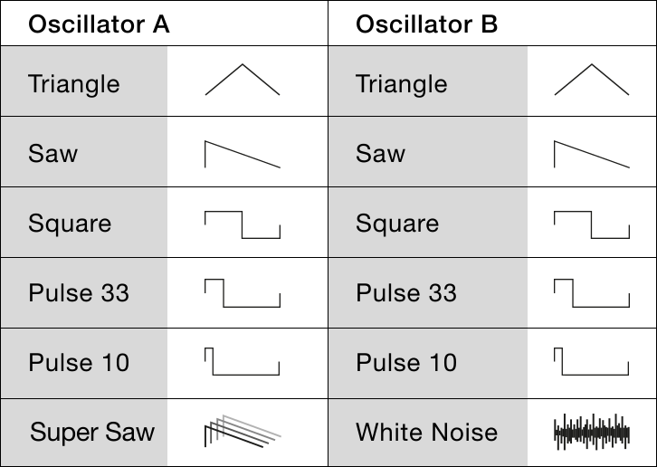
DETUNE
Detune adjusts the tuning of the two oscillators relative to each other, within a range of 0 to 10. Use lower settings for subtle vintage sounds, and higher settings for severely detuned effects. With the Super Saw waveform selected, this parameter controls the amount of detune within the large group of sawtooth waveforms that make up the sound.
To achieve a phase locked, dual oscillator setup, make sure that Detune is set to 0, and select one of the following pitch options for the Semi parameter -24, -12, -5, 0, +7, +12, +19, +24
SEMI
The Semi (Semitone) parameter sets the pitch of Oscillator B, in semitone steps. Use -12 or -24 for a classic sub setup, +7 for a fifth tuning, or any other desired interval.
MIX (PAGE 2)
Mix determines the level balance of Oscillators A and B, from Oscillator A only at -10 to Oscillator B only at +10. With Mix set to 0, there is a 50/50 mix of both oscillators.
Range: -10 to +10
PAGE 3 & 4 – AMP & FILTER ENVELOPES
Apart from being adjustable from the panel, using the dedicated Envelope and Focus controls, both the Amp and Filter Envelopes can be adjusted from page 3 and 4 respectively. Use the soft buttons to focus an envelope stage, and the PROGRAM dial to adjust it.

PAGE 5 & 6 – FILTER, FILTER DRIVE
Page 5 contains settings for Filter Cutoff Frequency (Freq), Resonance (Res), Filter Envelope Amount (EnvAmt) and Keyboard Track (KbTrk) all of which except Keyboard Track are also adjustable from the panel using their dedicated knobs.
On page 6 is the Filter Drive setting, also available from the panel by turning Shift+Resonance.

FM
The basic principle behind frequency modulation (FM) synthesis is that one sine oscillator (the modulator) modulates the frequency of another (the carrier). The carrier can in turn modulate the frequency of yet another oscillator, etc. The resulting waveform is far more rich in harmonics than the original waveform, and drastic changes in tonal character are possible by altering the amount of modulation.
Traditionally, FM oscillators are referred to as operators, and the FM categories of the Nord Electro 7 provide algorithms with 2, 3 and 4 operators.
BODY AND SPECTRA
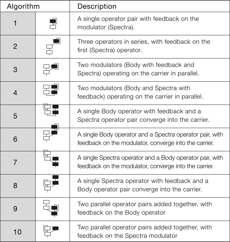
For all algorithms with more than two operators, the terms Body and Spectra are used for referring to the adjustable modulators. In very general terms, this reflects how each modulator is commonly used in sound design, where the Body parameter determines the strength and character of the fundamental and lower harmonics and the Spectra parameter determines the amount and character of upper harmonics. All parameters governing the Body and Spectra operators are further described below.
FOCUS AND VELOCITY
The FOCUS button toggles the edit focus for the Body and Spectra operators, with these panel controls following the current focus:
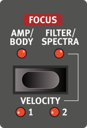
- Envelope ATTACK, DECAY/SUSTAIN, RELEASE
- Envelope Amount (ENV AMT)
The Body envelope doubles as Amp Envelope for FM sounds.
Pressing Shift+Focus turns on VELOCITY control for both FM envelopes. There are three Velocity amounts to choose from – 1, 2 and 3 (both LEDs being lit).
ABOUT THE FM EDIT VIEW
To access the Edit View for an FM synth sound, press EDIT|USER (Shift+Sound Select dial). Settings in the Edit view are selected using the soft buttons, and changed using the PROGRAM dial. The Edit View contains a number of pages, each grouping together related parameters.These are all outlined below, and are navigated using the PAGE buttons.
PAGE 1 – FM ALGORITHMS, AMOUNT, DRIVE
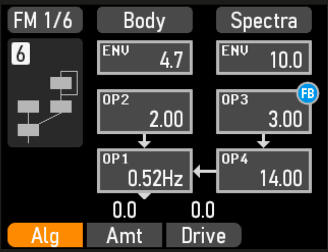
ALGORITHM (ALG)
There are ten distinct FM algorithms to choose from, available by focusing the Alg soft button:
AMOUNT (AMT)
The Amt (Amount) parameter determines the amount of static modulation applied by the Spectra and Body operators, for any given algorithm. This parameter is also adjustable from the panel, using the FM AMT (FM Amount) knob.
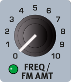
Using the 2-Op algorithm, with FM Amount at zero, FM Envelope Amount at zero and no feedback a pure sine wave is produced. Increasing the FM Amount increases harmonics.
DRIVE
Overdrive can be applied to the FM sound, independent of the Effects section, by adjusting the Drive parameter – highly useful for giving an expressive, organic quality to the sound.
PAGE 2 – OPERATORS AND PARTIALS
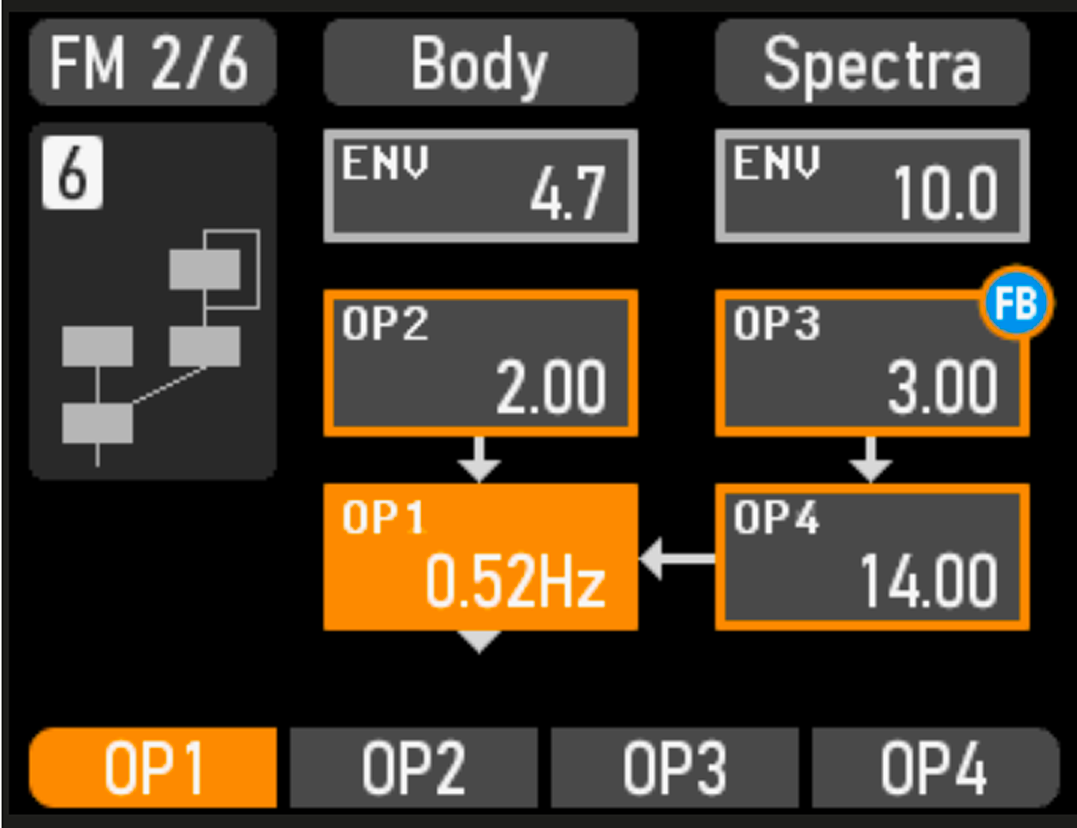
On page 2 the partial for each operator in the selected algorithm is set. Use the OP1-OP4 soft buttons to focus an operator, and use the Program dial to adjust the partial number, which is expressed as a multiple of the fundamental (1.00).
In addition to the partial settings, a range of fixed frequencies are available, after the final partial option (24.00). The available ranges differ between Operators 2 and 3 and Operators 1 and 4.
Range, partials OP 2, OP3: 0.25, 0.50, 0.75, 1.00, 1.25, 1.50, 1.75, 2.00, 2.25, 2.50, 2.75, 3.00, 3.50, 4.00, 4.50, 5.00, 5.50, 6.00, 7.00, 7.50, 8.00, 8.50, 9.00, 10.00, 11.00, 12.00, 14.00, 16.00, 20.00, 24.00
Range, fixed frequencies OP2, OP3: 35 Hz to 950 Hz
The fixed frequencies are useful for adding a non-keyboard tracking element to the FM sound, for instance when replicating the mechanical component of an electric piano sound, or for inharmonic, metallic sounds.
The fixed frequencies for OP1 and OP4 have been chosen from a lower frequency range than those for OP2 and OP3, appropriate for slowly fluctuating sounds.
Range OP1, OP4: 0.50, 1.00 to 15.00, 0.30 Hz to 5.55 Hz
PAGE 3 – FEEDBACK, ENV AMOUNT, BALANCEv
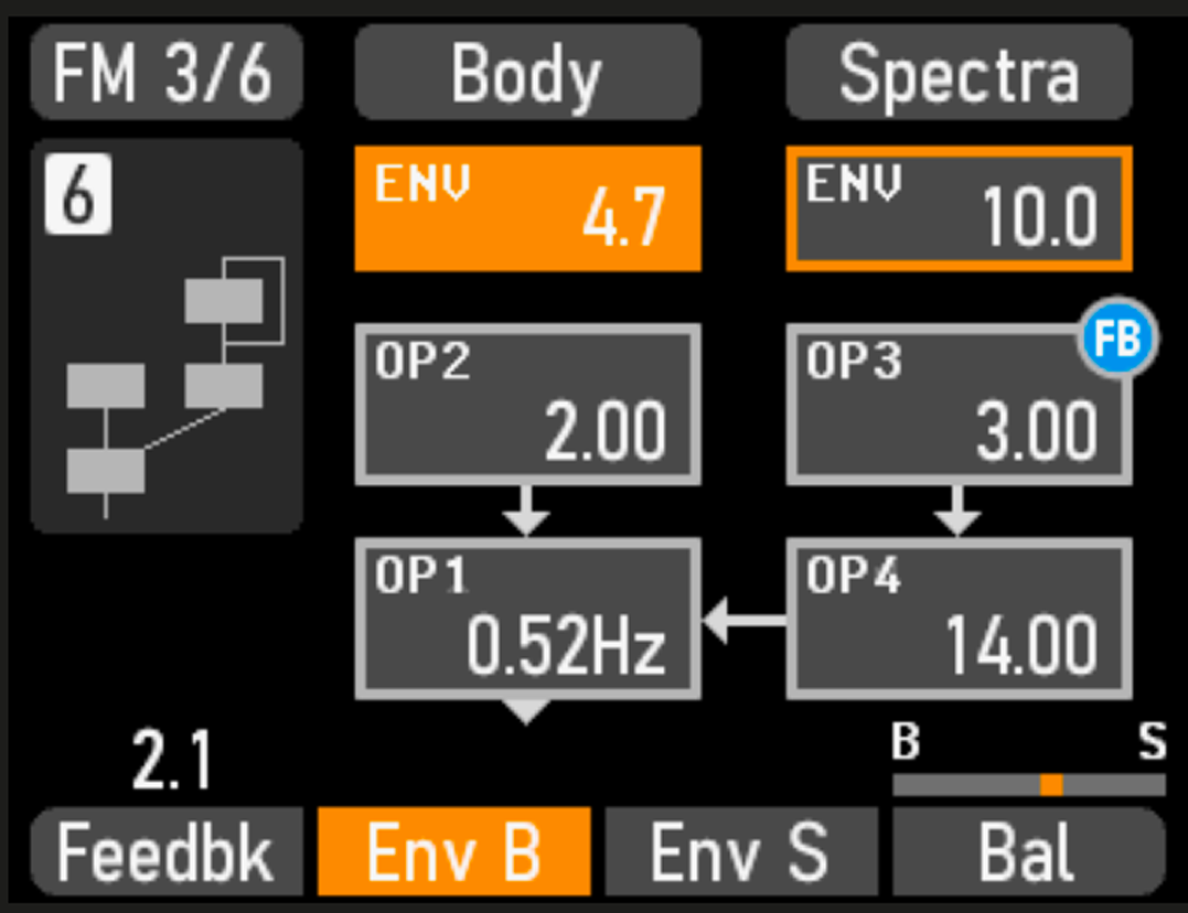
FEEDBACK
All algorithms come with a Feedback parameter, which introduces self-modulation – feedback – for the operator indicated by the circular FB icon. In general, using feedback is a way of increasing the amount and complexity of harmonics.
Range: 0.0 to 10.0
ENVELOPE AMOUNTS (ENV B, ENV S)
The Env B and Env S soft buttons focus the Envelope Amount control for the Body and Spectra envelopes respectively.
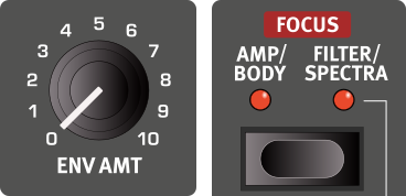
These controls determine the amount of modulation applied by each envelope, and can also be adjusted from the panel using the ENV AMT knob. In that case, which envelope is being controlled depends on the Envelope FOCUS.
BALANCE
The Balance parameter determines the relative levels of the Body and Spectra sides of the algorithm respectively.
Range: -10.0 to +10.0
PAGE 4 & 5 – ENVELOPES
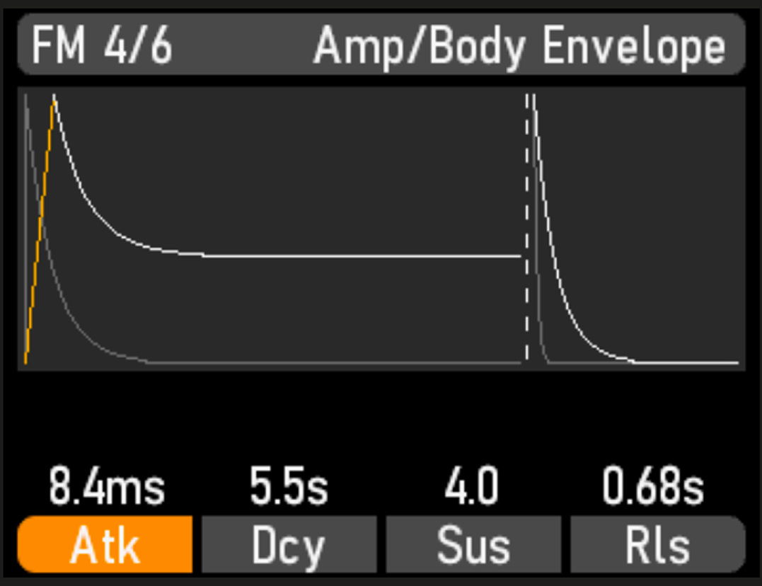
Apart from being adjustable from the panel, using the dedicated Envelope and Focus controls, both the Amp/Body and Spectra Envelopes can be adjusted from page 4 and 5 respectively. Use the soft buttons to focus an envelope stage, and the PROGRAM dial to adjust it.
For most FM algorithms, the Amp envelope doubles as an additional FM envelope, used for the modulation applied by the Body operator within that algorithm. See the previous “Body And Spectra” section for further details.
PAGE 6 – KEYBOARD TRACKING
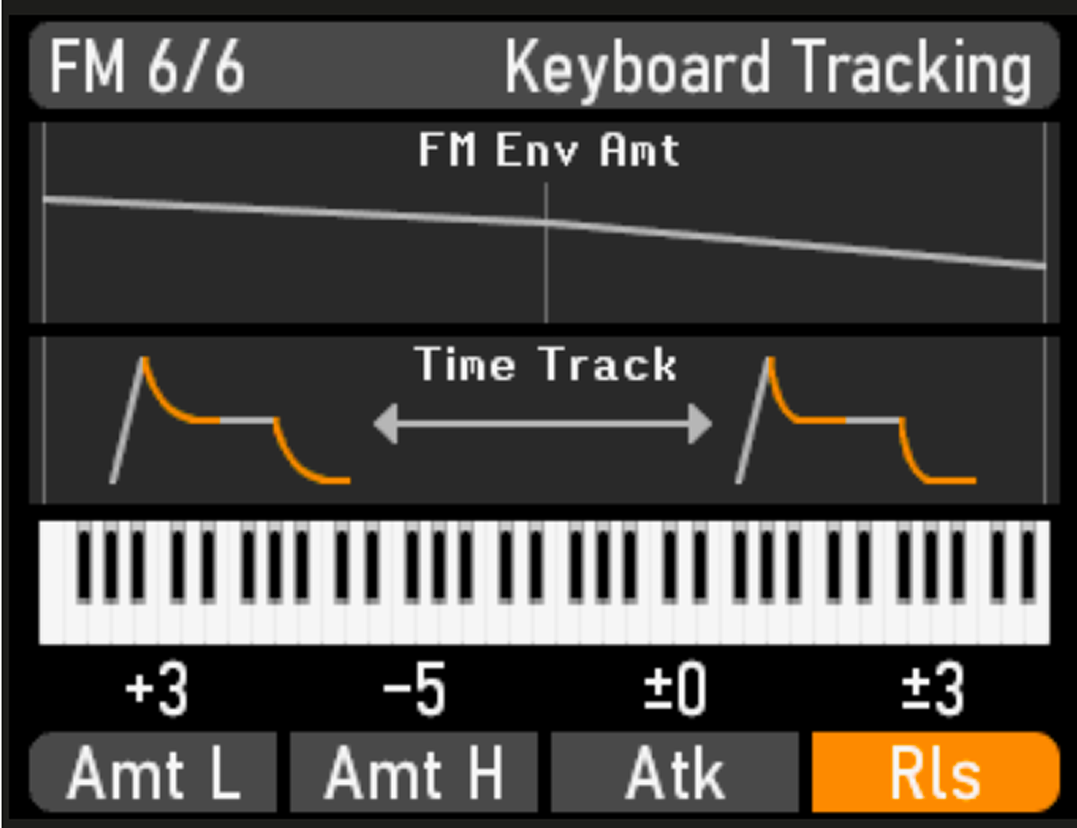
The Keyboard Tracking page contains settings for adjusting the response of the FM sound across the keyboard, useful for maintaining the desired timbre across different registers.
FM ENV MODULATION AMOUNT (AMT L, AMT H)
The Amt L (Amount Low) parameter controls the amount of modulation scaling for the range below middle C and can be set from 0 (no modulation scaling) to positive values up to 10, which increases the amount of modulation (and therefore often the brightness) for lower notes.
Range: 0 to 10
The Amt H (Amount High) parameter controls the modulation scaling for the range above middle C, from 0 (no scaling) to negative values down to -10, gradually decreasing the amount of modulation for notes in the upper range
Range: 0 to -10
With both parameters at zero, the modulation index is the same regardless of register.
ENVELOPE KEYBOARD TRACKING (ATK, RLS)
The Attack (Atk) parameter introduces a difference in envelope Attack time from low to high notes on the keyboard, making it longer for lower notes and shorter for higher notes.
Range: 0 to +/-10
The Decay/Release (Rel) parameter introduces a difference in envelope Decay and Release times from low to high notes on the keyboard, making the times longer for lower notes and shorter for higher notes.
Range: 0 to +/-10
With both parameters at zero, all envelope times are static regardless of played note.
THE ENVELOPES
The envelopes are used for shaping the sound over time, from when a key is played to after it has been released. The diagram below illustrates the role of each parameter - attack, decay, sustain and release - throughout the course of the total envelope time.
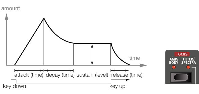
The Synth section has two separate envelopes, the AMP/BODY envelope and the FILTER/SPECTRA envelope. Use the FOCUS button to toggle the edit focus between them.
The AMP envelope controls the sound level or amplitude of the Synth sound over time.
With a Sample or Analog sound, the FILTER envelope modulates the filter cutoff frequency over time.
With an FM sound, the SPECTRA envelope controls the amount of modulation applied by the Spectra operator.
The envelopes are visualized by the display when edited, with the focused envelope overlayed on top of the non-focused one. This makes it easy to sync or compare settings for one envelope in relation to the other.
ATTACK, DECAY, SUSTAIN AND RELEASE
Both envelopes have their distinct settings for Attack, Decay, Sustain and Release, and the principles for how they work is the same for both.
ATTACK
Attack sets the time it takes for the envelope to reach maximum level after a key has been pressed. Turning the ATTACK knob clockwise increases the Attack time.
DECAY
When the attack phase is over, and the key is still held down, the envelope amount begins dropping down to the Sustain level. Use the DECAY knob to set the time this should take. If the Decay time is set to maximum, the envelope will be in Sustain mode, meaning that it stays on a constant value until the key is released.
SUSTAIN (SHIFT+DECAY)
After the Decay phase, the envelope amount remains at the level defined by the SUSTAIN (Shift+Decay knob) parameter until the key is released.
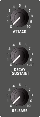
Samples load with the Sustain level set to zero, but with Decay set to its maximum value, which corresponds to a sustaining sound. This allows for quickly creating a decaying sound, by lowering the Decay time, without altering the Sustain level.
RELEASE
When the key is released, the envelope enters the release stage. The release time determines how long it takes the envelope to reach its minimum value and is set with the RELEASE knob.
ENVELOPE AMOUNT (ENV AMT)
For FM sounds, the ENV AMT control determines the amount of modulation applied by the Body and Spectra envelopes respectively, depending on the Envelope FOCUS. For ANALOG sounds, and SAMPLES if the Filter has been turned on, Env Amt determines the amount of modulation applied to the Filter by the Filter Envelope.
FILTER
The Nord Electro 7 features a 24 dB per octave, resonant low-pass filter. This is one of the most commonly used filter types in analog synthesis, providing a wide range of classic sounds.
The Filter can be turned On or Off for Samples, by pressing FILTER ON Shift+Vibrato.
All Filter settings are also available from the Edit|User views for Samples and Analog sounds.
In Analog mode the Filter is always On and in FM mode the Filter is not applicable.
FILTER FREQUENCY
The filter FREQ knob is used for setting the cut-off frequency point – that is where in the frequency range the filter begins to process frequencies. The actual result of this processing depends on the type of filter used.
FILTER FREQUENCY
The filter FREQ knob is used for setting the cut-off frequency point – that is where in the frequency range the filter begins to process frequencies. The actual result of this processing depends on the type of filter used.
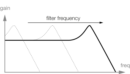
The image above illustrates three different Filter Frequency settings using a low pass filter. The area to the left of the downward slope indicates frequencies that pass through the filter. The area to the right of the slope are those frequencies that are reduced. The “humps” at the top indicate a resonance setting.
KEYBOARD TRACKING (KBTRK)
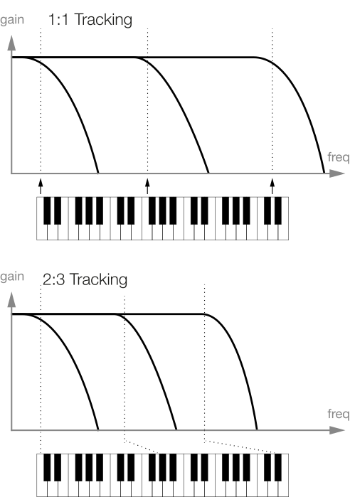
The Keyboard Tracking (KbTrk) parameter is found on the Filter page in the EDIT|USER views for Analog and Sample sounds. The reason for controlling keyboard tracking is related to basic acoustics. If the pitch of a waveform is raised, the harmonics naturally raise in frequency as well. If the cutoff frequency is constant, the sound will be perceived as getting “muddier” the higher up the keyboard you play. To avoid this effect, use Key Tracking.
KEY TRACKING SETTINGS
- Off: The filter frequency cut-off point is not altered by the note played.
- 1/3: The cut-off frequency tracks the keyboard in a 1:3 relationship. Play one octave higher and the cutoff frequency will move by 1/3 of an octave.
- 2/3: The cut-off frequency tracks the keyboard in a 2:3 relationship, play one octave higher and the cutoff frequency will move by 2/3 of an octave.
- 3/3: The cut-off frequency tracks the keyboard at a 1:1 ratio.
FILTER RESONANCE
The Resonance (RES) parameter is used to further adjust the characteristics of the filter. Increasing the Resonance will emphasize frequencies around the cutoff frequency, making the sound thinner.
Further raising the Resonance will make the sound resonant to a point where the filter starts to self-oscillate and produce a ringing pitch. Exactly where in the frequency spectrum this “ringing” occurs, depends on the Frequency value.
FILTER DRIVE
Activating Filter DRIVE (Shift+Resonance knob) adds distortion to the Filter stage. The Drive parameter is also adjustable from the second Filter page in Analog and Samples Edit View.